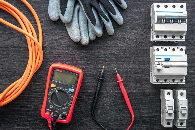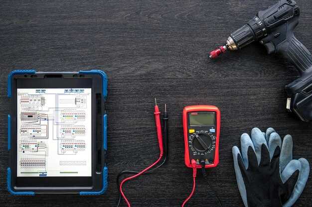
Understanding the electrical system of a vehicle is crucial for any car enthusiast or mechanic. Electrical failures can manifest in various forms, from dim headlights to malfunctioning sensors, and often stem from underlying wiring issues. A multimeter serves as an essential tool in diagnosing these problems, providing valuable insights into the vehicle’s electrical health.
When faced with electrical gremlins, many car owners may feel overwhelmed. However, the good news is that diagnostic procedures using a multimeter can simplify the troubleshooting process. This article will delve into the fundamental techniques for identifying car wiring issues, emphasizing practical applications of the multimeter. By mastering these techniques, you can efficiently pinpoint faults, whether they originate from corroded connections, broken wires, or faulty components.
We will explore key concepts such as measuring voltage, resistance, and continuity, which are pivotal in diagnosing wiring problems. Additionally, the article will provide a step-by-step guide on how to systematically approach wiring issues, ensuring that you can restore your vehicle’s electrical system to optimal condition.
Understanding Multimeter Functions for Automotive Diagnostics

A multimeter is an essential tool for diagnosing automotive wiring issues, providing various functions to measure voltage, current, and resistance. Understanding these functions will enhance your ability to troubleshoot electrical problems efficiently.
The primary function of a multimeter is to measure voltage, which can be either AC or DC. In automotive applications, most electrical systems operate on DC voltage. By selecting the DC voltage setting on the multimeter, you can check the battery voltage and ensure it is within the acceptable range (usually around 12.6 volts for a fully charged battery). Additionally, testing the voltage at different points of the wiring harness can help identify issues like voltage drops that may indicate corroded connections or damaged wires.
Another vital function is current measurement, which allows you to assess how much electric current flows through a circuit. This measurement is crucial when diagnosing components such as motors or lights that may draw more current than intended, leading to overheating or failure. To measure current, the multimeter must be connected in series with the circuit, which requires a basic understanding of circuit configuration to avoid damage to the multimeter or the vehicle’s electrical system.
Resistance measurement is also critical in automotive diagnostics. By measuring resistance in ohms, you can determine if components like sensors, switches, or coils are functioning correctly. A high resistance reading may indicate an open circuit or a faulty component, while a low resistance reading might suggest a short circuit. It is essential to disconnect power before measuring resistance to prevent damage to the multimeter and ensure accurate readings.
Many multimeters also have a continuity test function that emits a beep when there is a complete circuit, making it easy to check for broken wires or faulty connections. This feature is particularly useful when tracing complex wiring assemblies, as it quickly identifies areas of concern without requiring detailed voltage readings.
Understanding the specific functions of your multimeter, including voltage, current, resistance, and continuity tests, will significantly improve your ability to diagnose and troubleshoot automotive wiring issues. Mastery of these measurements enables precise identification of faults, ultimately leading to effective repairs and enhanced vehicle reliability.
Identifying Common Wiring Problems Using Voltage Measurements

Using a multimeter to measure voltage is an effective way to diagnose common wiring problems in vehicles. Voltage measurements can help identify issues such as broken wires, poor connections, and faulty components. The following steps outline how to use voltage measurements to identify these common wiring problems.
First, ensure the multimeter is set to the correct voltage range. When diagnosing automotive wiring, it’s typically best to use the DC voltage setting. Start by checking the battery voltage to confirm it is within the expected range (usually around 12.6 volts for a fully charged battery). A significantly lower voltage indicates a potential issue with the battery or charging system.
Next, inspect the wiring harness for any visible damage. Look for frayed wires, corrosion, or loose connections. After visual inspection, use the multimeter to measure voltage at various points along the wire. Begin at the power source and work your way to the component you’re testing. For example, if you suspect an electrical component is not receiving power, measure the voltage at the component’s connector. If the voltage reading is zero or significantly lower than expected, this points to a wiring issue.
Another common issue is voltage drop, which can occur due to corrosion or poor connections. To test for voltage drop, measure the voltage at each end of a wire. A difference in voltage between the two points indicates a problem, such as high resistance at a connection. Ideally, there should be minimal voltage drop across any wire or connector in the circuit.
Short circuits can also lead to significant voltage issues. If you suspect a short circuit, measure the voltage on the wire leading to the affected component. If the voltage is much lower than expected, it may indicate a short to ground. In this case, isolating the circuit and testing individual components can help locate the source of the problem.
Finally, always refer to the vehicle’s wiring diagram for reference values and expected voltage readings at various points in the electrical system. Understanding these specifications will aid significantly in accurately diagnosing wiring problems using voltage measurements.
Testing Continuity and Resistance to Detect Faulty Connections
To effectively diagnose wiring issues in a vehicle, testing continuity and resistance using a multimeter is essential. Continuity testing allows you to determine whether an electrical path is complete, while resistance measurements can help identify problematic connections that might cause electrical failures.
To begin, set your multimeter to the continuity or resistance mode. Continuity testing is typically indicated by a sound or LED light when a complete circuit is detected. If your multimeter has a specific continuity setting, use that for the test. For resistance measurements, choose the ohm (Ω) setting.
Start by disconnecting power to the circuit you are testing to prevent any electrical shock or damage to the multimeter. Identify the two points in the circuit where you want to check continuity, such as a connector or wire end. Touch one probe to the first point and the other probe to the second point. If the multimeter beeps or shows a low resistance value (close to zero ohms), the path is complete. A lack of sound or a reading of infinite resistance indicates a break in the circuit.
For resistance testing, place the probes on either side of the connection being tested. A high resistance reading might indicate corrosion or poor contact at the connection point. Generally, a resistance value above a few ohms can signify a fault, as healthy connections should ideally register near zero ohms.
It is important to document your findings for each connection tested. Analyzing these readings will help pinpoint faulty wires or connectors, allowing for effective repairs. Continuity and resistance testing are indispensable techniques that provide insight into the integrity of a vehicle’s electrical system.


